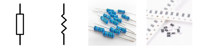
A resistor is a basic component in a circuit. Its main function is to resist the flow of electric current. The unit of resistance is ohm (Ω), which is the ratio of voltage (V) to current (A), expressed as R = V / I. There are many types of resistors, including fixed resistors, variable resistors, and special types like thermistors and photoresistors. A resistor converts electrical energy into heat, so it is an energy-consuming component that generates heat when current passes through it.
In circuit design, resistors are used to control current and voltage, divide voltage, and act as signal attenuators. Both AC and DC signals can pass through resistors. The power rating of a resistor is also important, as it indicates the maximum power the resistor can handle without being damaged. When choosing a resistor, you need to consider not only its resistance value but also its power rating and its specific function in the circuit.
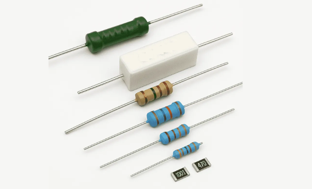
Depending on their structure, materials, and applications, resistors can be classified into various types, including carbon film resistor, metal oxide film resistor fixed resistors, variable resistors, adjustable resistors, through-hole resistors, chip/resurface mount resistors, thermistors, photoresistors, power resistors, precision resistors, varistors, and more.
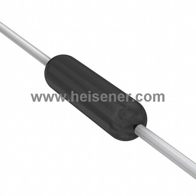
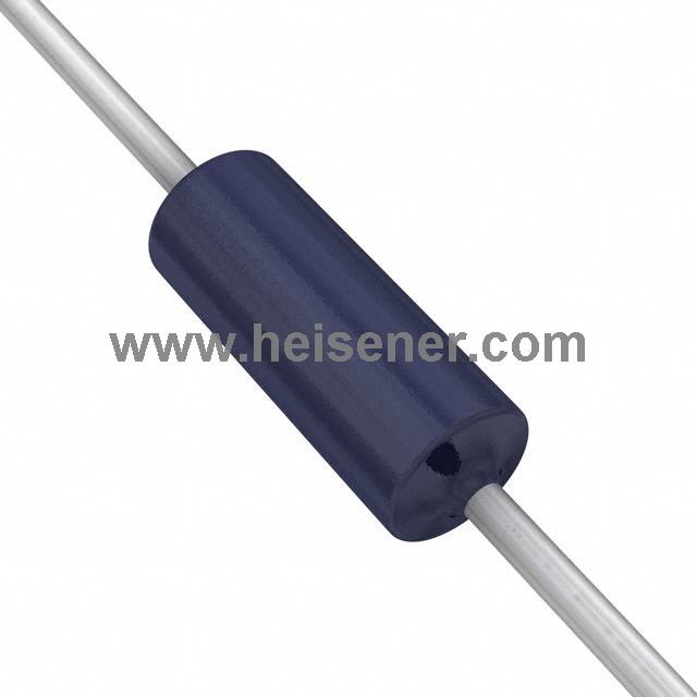
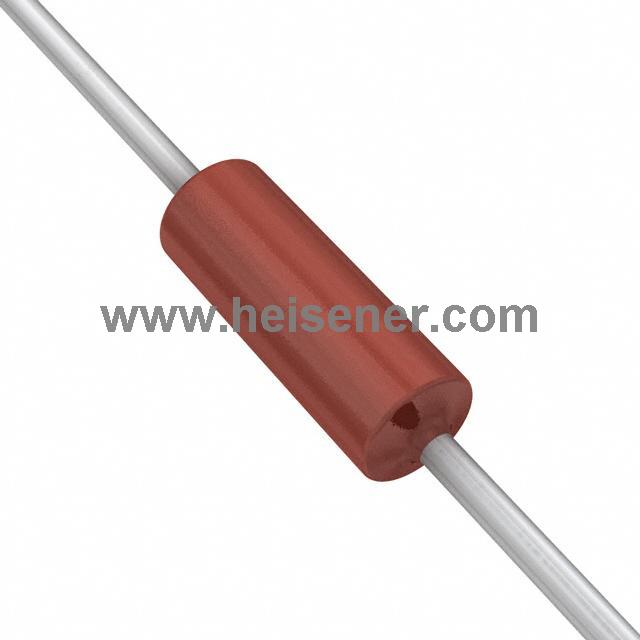
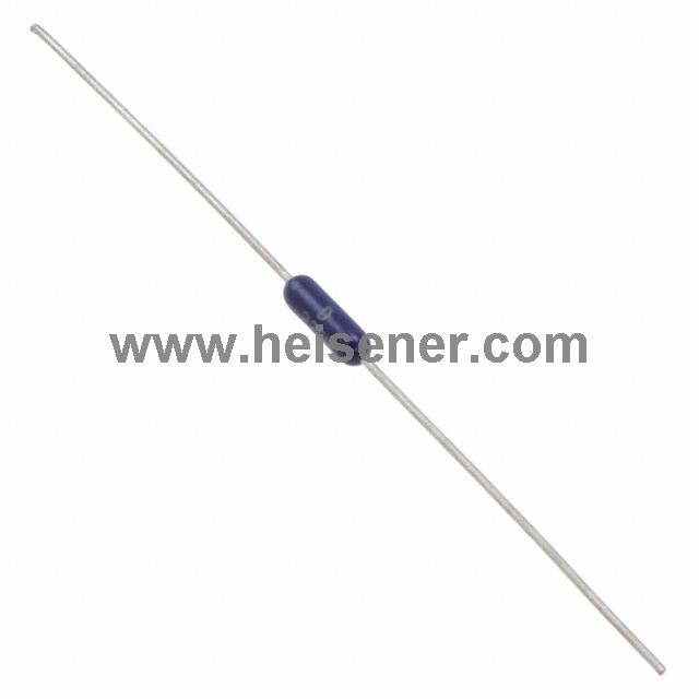
A carbon film resistor is made by coating a ceramic tube with a layer of carbon, depositing crystalline carbon onto a ceramic rod. Carbon film resistors are low-cost, stable in performance, have a wide resistance range, and exhibit low temperature and voltage coefficients. They are currently the most widely used type of resistor.
Metal film resistors are made by coating a ceramic tube with a layer of metal, using vacuum evaporation to deposit an alloy material onto the ceramic rod. Metal film resistors have higher accuracy, better stability, lower noise, and smaller temperature coefficients than carbon film resistors. They are widely used in instruments and communication equipment.
The metal oxide film resistor is made by coating a ceramic tube with a layer of tin oxide, depositing a metal oxide layer on an insulating rod. Because it is an oxide, it remains stable at high temperatures, resists thermal shock, and has strong load capacity. According to applications, it can be general-purpose, precision, high-frequency, high-voltage, high-resistance, high-power, or used in resistor networks.
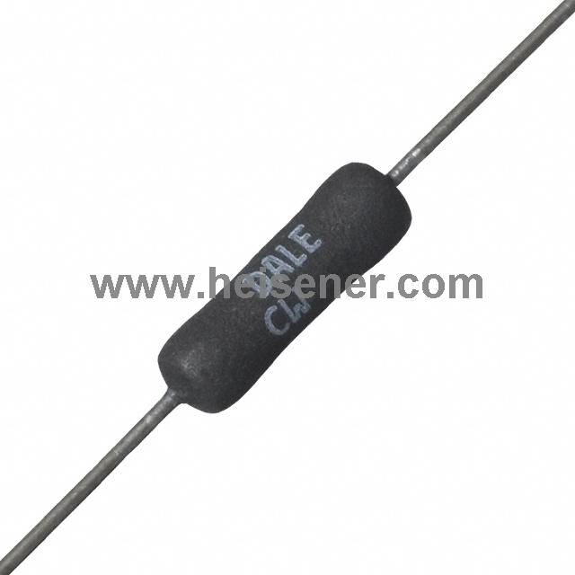
These resistors are made by winding a resistive wire around an insulating frame, coated externally with a heat-resistant glaze or insulating paint. Wirewound resistors have low temperature coefficients, high resistance accuracy, good stability, and are heat- and corrosion-resistant. They are mainly used for precision high-power resistors. Their drawbacks include poor high-frequency performance and large time constants.
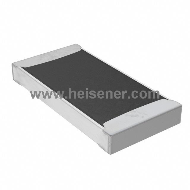
The thick film resistor is made by coating a ceramic substrate with a conductive paste, which is then sintered at high temperature to form the resistor. It features low cost, high voltage resistance, and suitability for mass production. It is widely used in general electronic circuits for basic functions such as current limiting and voltage division.
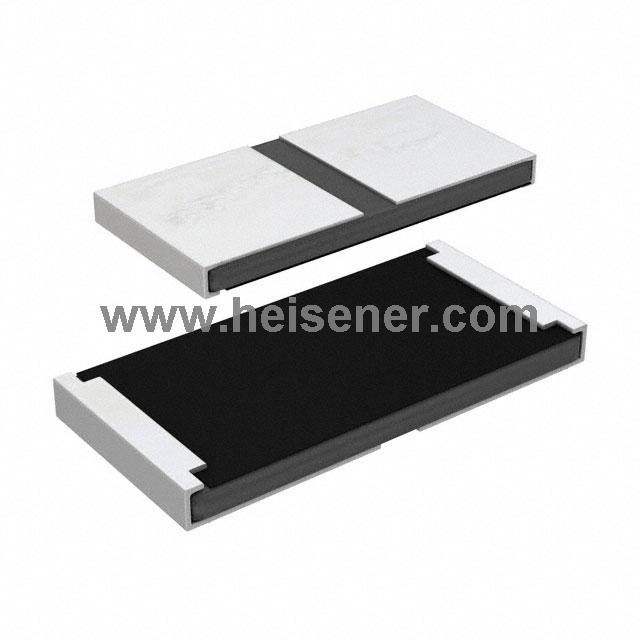
This type of resistor is made by evaporating or sputtering a uniform layer of metal or metal oxide onto a ceramic substrate. It offers high precision, high stability, and low noise, making it mainly suitable for instruments and precision electronic equipment.
A carbon composition resistor is made by pressing a mixture of carbon powder and synthetic resin. It is one of the earliest types of resistors. It can withstand high surge currents, making it suitable for circuits that require impact current resistance, serving functions such as current limiting, voltage division, and circuit protection.
Fixed resistors are resistors with a set resistance value that cannot be changed. They are used to limit current, divide voltage, and stabilize circuits. Common types include carbon film, metal film, metal oxide film, wirewound, thick film, thin film, and carbon composition resistors.
Variable resistors are used to adjust voltage distribution in a circuit. By rotating a knob or sliding a wiper, the position of the wiper on the resistive element changes, altering the resistance between the wiper and the two fixed ends. This allows flexible control of current or voltage in the circuit.
Adjustable resistors are a type of variable resistor that can be manually set to a desired resistance value and then fixed in place. They are commonly used for calibration, tuning, or setting operating points in electronic circuits. Examples include trimmer resistors and preset potentiometers.
A through-hole resistor is a type of resistor with leads that pass through holes in a circuit board and are soldered in place. They are usually larger in size, can handle higher power, and are easy to install or replace manually. They are suitable for DIY circuits or applications requiring higher power.
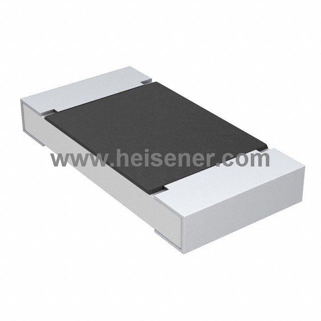
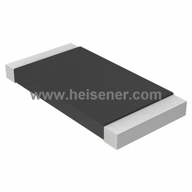
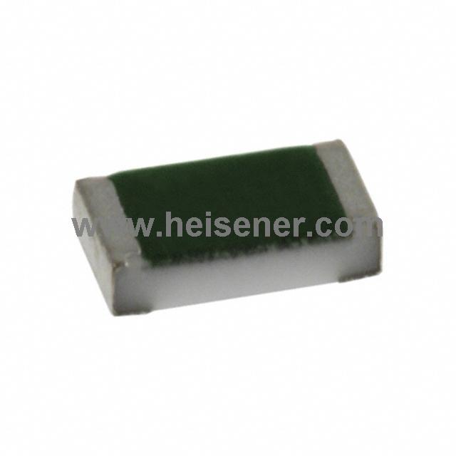
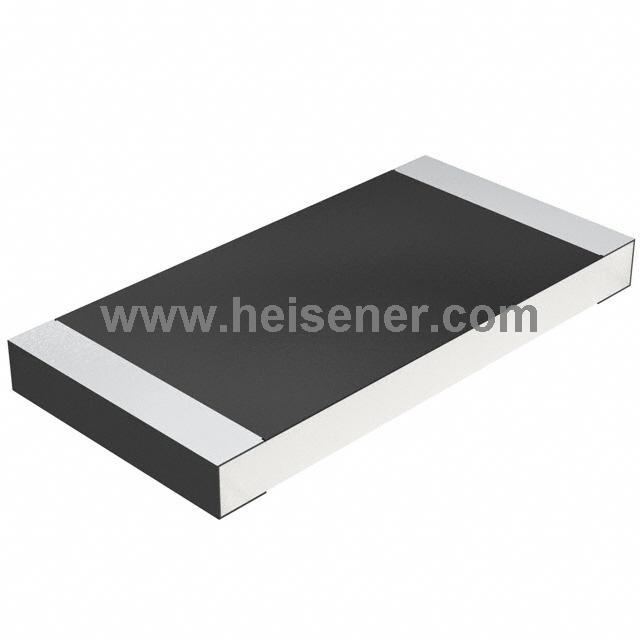
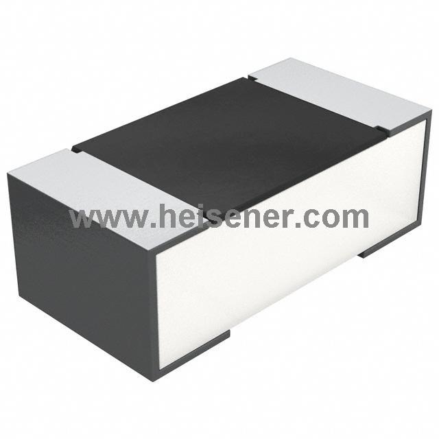
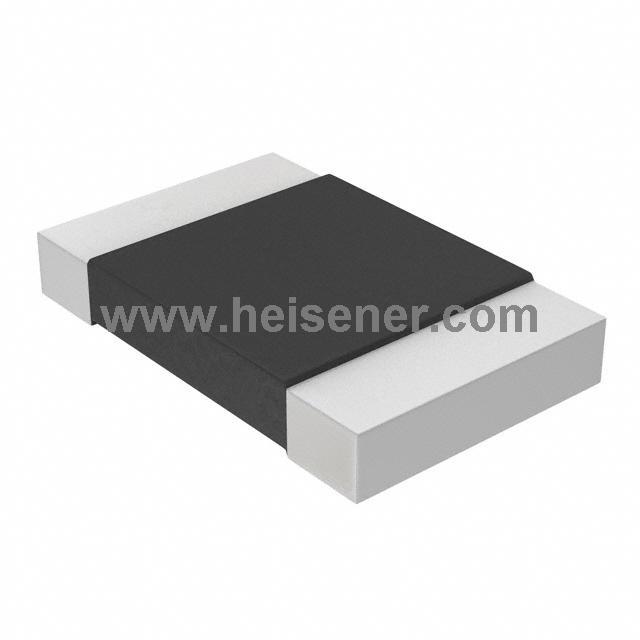
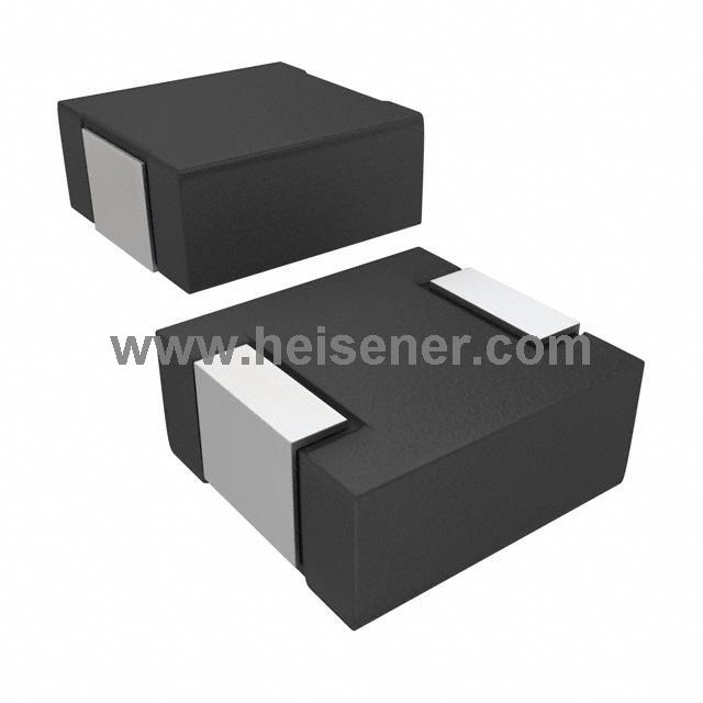
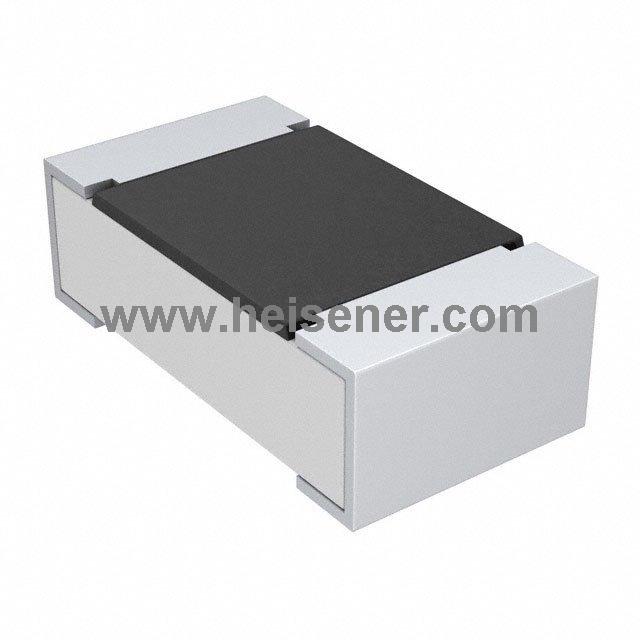
A chip resistor, also known as a surface mount resistor (SMD resistor), is directly soldered onto the surface of a circuit board using surface-mount technology. It is small in size, lightweight, and suitable for automated production. While it handles lower power compared to through-hole resistors, it is widely used in modern high-density electronic circuits.
A general-purpose resistor is a standard resistor used in most electronic circuits for functions such as current limiting, voltage division, and basic circuit stabilization.
A precision resistor is designed to have a very accurate and stable resistance value with minimal tolerance. It is used in circuits where exact resistance is critical, such as in measurement instruments, calibration circuits, and precision electronic devices.
A power resistor is designed to handle large amounts of electrical power without damage. They are typically larger in size, with excellent heat dissipation.
A thermistor is a resistor whose resistance changes significantly with temperature. Thermistors are usually made from metal oxide semiconductor materials, which are highly sensitive to temperature. They are divided into two main types: Positive Temperature Coefficient (PTC) thermistors and Negative Temperature Coefficient (NTC) thermistors. In NTC thermistors, resistance decreases as temperature rises.
A photoresistor is a resistor whose resistance changes according to the intensity of incident light. When light intensity increases, the resistance decreases; when light intensity decreases, the resistance increases.
A varistor is a resistor designed to protect circuits against voltage surges by changing its resistance with applied voltage. It is commonly used for surge suppression and transient voltage protection.
A resistor network or array is a group of multiple resistors packaged together in a single component. It is used to save space and simplify circuit design, commonly found in digital circuits and logic boards.
A shunt resistor is a low-resistance resistor used to measure current by producing a small voltage drop proportional to the current flowing through it.
The first function is current limiting. According to U=IR, if the voltage UUU remains constant, changing the resistance RRR will also change the current.
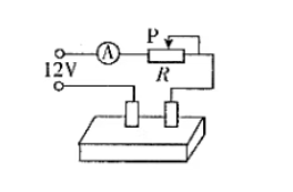
The second function is voltage division and current sharing.
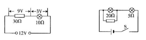
Series voltage division does not divide current; the current remains the same, and the input voltage Uin=Ur+U1. Suppose our light bulb is a 3V bulb and we only have a 12V battery. Connecting the bulb directly would burn it out. At this time, a series resistor can be used for voltage division. How much voltage should be divided? We know that 9V needs to be divided, the voltage across the bulb is 3V, and the resistance is 10 ohms, so the current is 0.3A. The series resistor needed can then be calculated as 30 ohms.
Next is the current division. Parallel current division does not divide voltage. The principle is the same and will not be elaborated here.
Resistors also have the function of converting electrical energy into heat energy: when current passes through a resistor, it converts all (or part) of the electrical energy into heat energy. Electrical appliances that convert electrical energy into heat are called electric heaters, such as soldering irons, electric stoves, rice cookers, heaters, and so on.
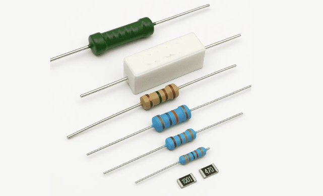
The material and structure should be chosen according to the circuit requirements: for high-frequency circuits, select resistors with low distributed inductance/capacitance, such as carbon film, metal film, metal oxide film, thin film, thick film, or alloy resistors; for high-gain small-signal circuits, select low-noise resistors, such as metal film, carbon film, or wirewound resistors.
The resistance value should be close to the calculated value for the circuit and preferably from a standard series. General circuits allow a tolerance of ±5%~±10%; precision circuits require precision resistors (accuracy ≤1%), such as 0.01%, 0.1%, or 0.5%.
The rated power should meet the circuit requirements. For power resistors, a rating 1–2 times higher than the actual circuit requirement can be selected.
Measure the actual resistance with a multimeter to check if it matches the nominal value, ensuring the error is within the allowable range.
Measurement precautions: select a suitable range so the pointer is near the middle of the scale; adjust to zero before measuring; avoid touching both ends of the resistor or the metallic parts of the probes to prevent errors.
If the measured resistance is close to the nominal value, the resistor is considered good; if the deviation is too large or there is no continuity, the resistor is defective.
Check whether the resistor's appearance is intact. Fixed resistors should have clear markings, no burns, cracks, or corrosion, and firmly connected leads. Potentiometers should have smooth and proper shaft rotation; for those with switches, ensure the switch operates normally.
a) Fixed Resistors:
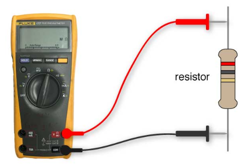
Use the resistance mode on a multimeter to measure. The measured value should be within the tolerance range of the rated value. If the resistance is too high, zero, infinite, or unstable, the resistor is faulty. Avoid touching both ends with your hands and always test with the power off.
b) Fuse and Sensitive Resistors:
A fuse resistor showing infinite resistance is blown. Thermistors change resistance with temperature, and photoresistors change resistance with light intensity. If no change occurs, the component is damaged.
c) Variable Resistors and Potentiometers:
Check the resistance between the two fixed terminals, which should be normal. When rotating the shaft, the resistance should change smoothly. Any sudden jumps or fluctuations indicate poor contact between the wiper and the resistive element.
For precise resistance measurement, use a digital bridge tester. Insert the resistor into the bridge terminal, select the proper range, and read the value directly from the display. This method is often used when custom-made resistors or adjusted fixed resistors require accurate resistance verification.