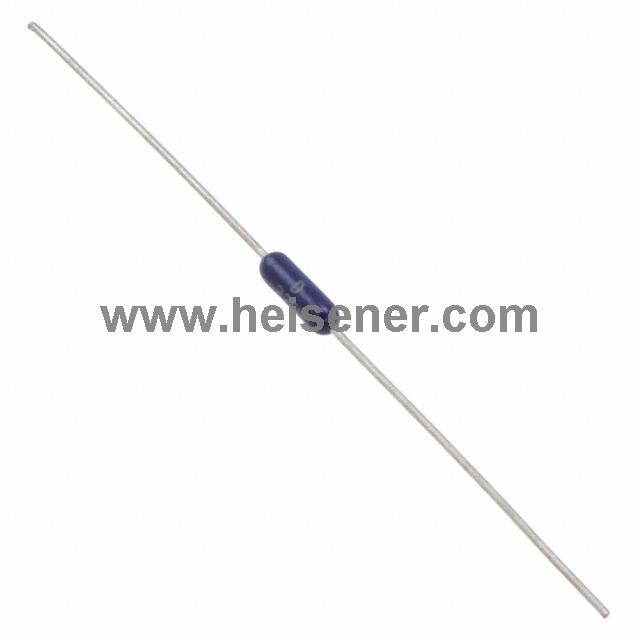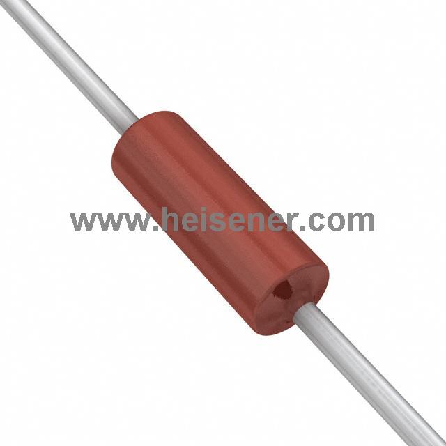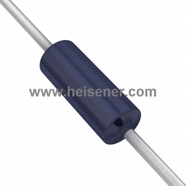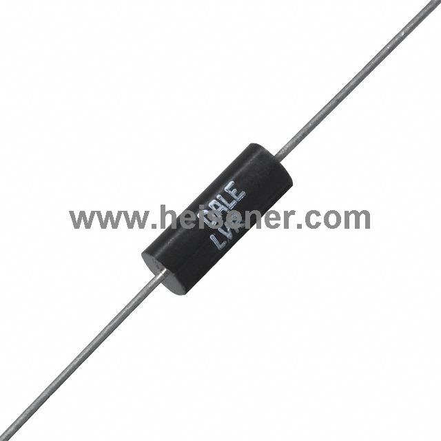
Through-hole resistors are electronic components with leads that pass through holes in a circuit board and are soldered in place. They are strong mechanically and have good heat dissipation. In semiconductor processes, the fully aligned via technology can reduce the resistance of through-hole resistors by up to 70%, and selective deposition can improve the metal interface resistance by removing the sidewall barrier layer.
In this article, Heisener will explain the definition, specifications, types, applications, and differences from surface-mount resistors, helping users better understand and choose the right through-hole resistors.
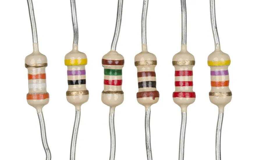
A through-hole resistor is a basic electronic component with leads that pass through holes in a circuit board and are soldered in place. It is used to limit current, divide voltage, or shunt voltage. The resistor is usually made of materials such as carbon film, metal film, or metal oxide film. When current flows through the resistor, it converts part of the electrical energy into heat, controlling the amount of current in the circuit.
Its working principle is based on Ohm’s Law: the voltage across the resistor is proportional to the current through it, V = I × R. As current passes through the through-hole resistor, a voltage drop occurs, protecting other components or providing the desired voltage division. Because it is mounted via leads through the circuit board, it offers strong mechanical stability and good heat dissipation.
Typically, the resistance and tolerance of a through-hole resistor are shown using color bands on the resistor itself. The values represented by the colors are as follows:

Resistance: This shows how much the resistor limits the flow of current. Measured in ohms (Ω), the higher the number, the more it resists the current. Metric prefixes such as milli (m) and kilo (K) may be used with the ohm value.
Tolerance: This indicates how much the actual resistance may differ from the stated value due to small variations in manufacturing. It is usually shown as a ± percentage. A smaller percentage means the resistor is closer to the stated value.
Power (Watts): The maximum power the resistor can handle. Exceeding this limit can damage the resistor and possibly other parts of the circuit. A resistor with higher power rating can replace one with a lower rating, but not vice versa.
Material: The type of material used to make the resistor.
Characteristics: Special properties of the resistor, such as flame resistance, high voltage tolerance, or current sensing.
Temperature Coefficient: The resistance of any material changes with temperature, usually increasing with heat and decreasing when cold. The temperature coefficient shows how much the resistance changes per 1°C, usually measured in parts per million (PPM).
Operating Temperature: The range of temperatures in which the resistor can work properly. Going below or above this range may cause instability, damage to the resistor, the device, or both.
Package / Case: The protective covering of the component, which makes handling, mounting, and protecting the resistor easier. This is the industry standard closest to the supplier’s package.
Supplier Device Package: The package defined by the manufacturer. These are manufacturer-specific, and it is best to use the actual dimensions from the datasheet when designing circuits.
Size / Dimensions: The physical measurements of the component, usually length and diameter.
Height – Mounting (Max): How far the resistor extends above the surface where it is mounted.
Number of Terminals: Shows how many terminals the resistor has for connection to the PCB.
Failure Rate: How often the component fails, usually shown as a percentage per 1,000 hours of use. The letters M, R, P, and S come from military standards and correspond to specific percentages.
Through-hole resistors are widely used in electronic circuits. Their main functions are to limit current, divide voltage, or shunt voltage. For example, in power modules, amplifier circuits, and industrial control systems, through-hole resistors are often used for voltage regulation, current limiting, and protecting other sensitive components, ensuring the system runs safely and reliably.
Through-hole resistors are also commonly used in precision measurement and signal conditioning circuits. They can maintain stable resistance even during long-term use or in high-temperature environments, ensuring signal accuracy and overall system performance. In instruments, automotive electronics, and communication devices, through-hole resistors are essential components.
The composition of a resistor determines whether it is suitable for your specific application. For through-hole resistors, Heisener offers a wide variety of materials, including thick film, carbide, carbon film, wire-wound, thin film, metal element, metal oxide film, metal foil, metal film, and ceramic resistors. For surface-mount resistors, available materials include thick film, carbide, carbon film, wire-wound, thin film, metal element, metal foil, and metal film.
Carbon Film Resistors
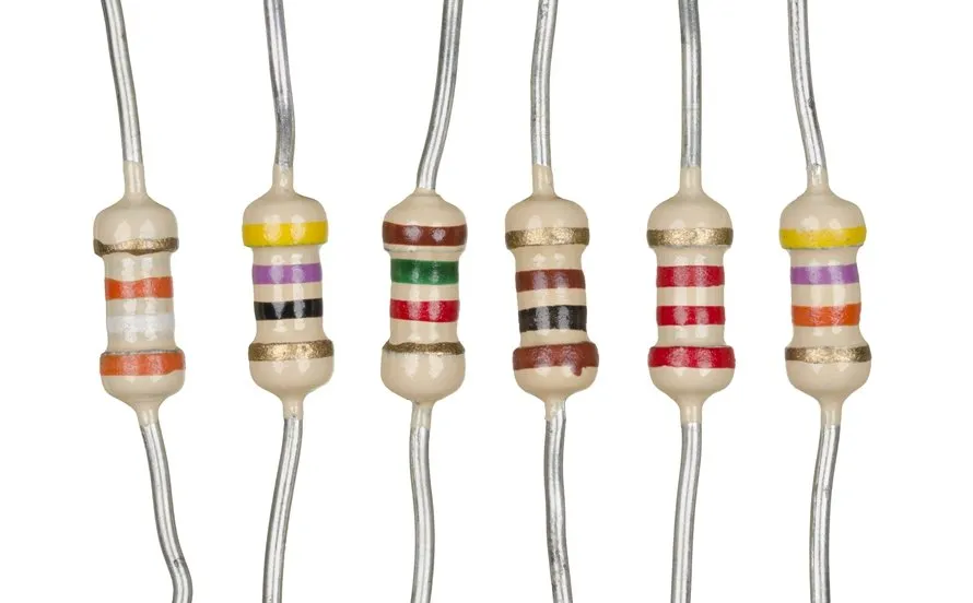
These resistors are generally larger in size, have lower power ratings, wider tolerances, and higher temperature coefficients. They may produce noise at high temperatures. On the positive side, they are cheaper than most resistors and often perform well at higher frequencies.
Ceramic Resistors
Ceramic resistors have a high temperature coefficient, a medium operating temperature range, and are usually more expensive than most resistors.
Metal Element Resistors
These resistors are commonly used for current sensing. They are highly accurate with low resistance values and tight tolerances.
Metal Film Resistors
Metal film resistors offer good temperature stability, low noise, a wide resistance range, and tight tolerances.
Metal Oxide Film Resistors
Similar to metal film resistors, they can handle surge currents more effectively and tolerate higher temperature levels.
Thick Film Resistors
Thick film resistors feature low noise, limited surge tolerance, good temperature stability, and high voltage ratings. They are available in a wide range of resistance values.
Thin Film Resistors
These resistors have low noise, long-term stability, low temperature coefficients, and can achieve high resistance values.
Wire-Wound Resistors
Wire-wound resistors are suitable for high-power and high-current applications. However, they tend to generate more noise and have lower resistance values. Non-inductive options are also available.
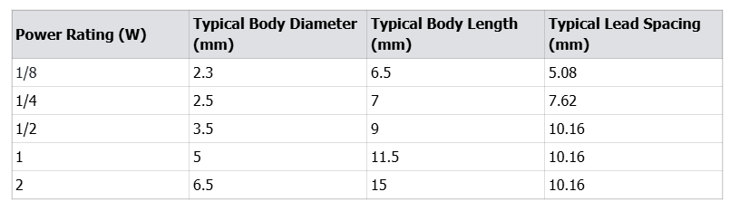
Through-hole resistors come in different physical sizes. Each size has a specific power rating. This is important for PCB design and component selection. The size of a resistor affects its heat dissipation and the space it occupies on the board.
The size of a standard through-hole resistor is usually determined by its power rating, measured in watts (W). Common ratings include 1/8W, 1/4W, 1/2W, 1W, and 2W. As the power rating increases, the diameter and length of the resistor increase, and the lead spacing becomes larger.
Through-hole resistors and surface-mount resistors differ in several key ways.
Through-hole Resistors
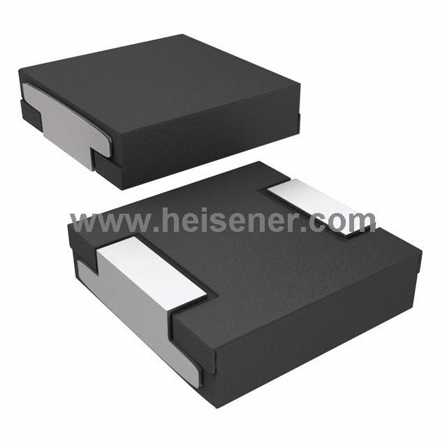
Through-hole resistors are installed by inserting their leads through PCB holes. They are larger in size, requiring more PCB space, and offer strong mechanical connections. This makes them suitable for manual assembly, prototyping, and high-power applications. They allow better heat dissipation through their leads, and installation tolerances can reach ±0.5 mm. However, their production and assembly costs are generally higher for large volumes.

Surface-Mount Resistors
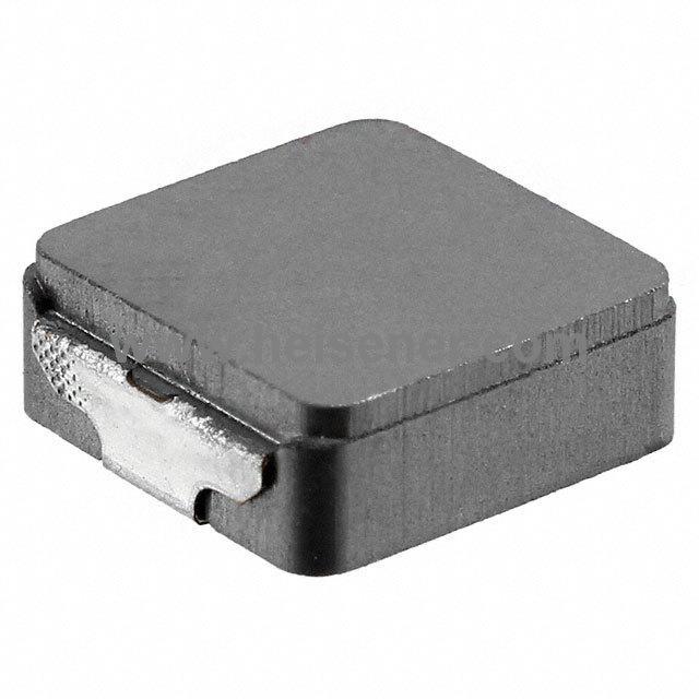
Surface-mount resistors, on the other hand, are soldered directly onto the PCB surface. They are much smaller—about 80% smaller than through-hole resistors—allowing higher component density and more compact PCB designs. SMT resistors rely on specialized automated equipment for assembly, have lower mechanical strength, and their heat dissipation depends largely on PCB design. They are ideal for high-density designs, large-scale production, and compact devices.
1. Determine the Resistance Value
The resistance value, measured in ohms (Ω), determines how much the resistor limits current in a circuit. It should be selected based on Ohm’s Law, R=V/I, where V is the voltage across the resistor and I is the desired current. Additionally, check that the resistor’s tolerance, such as ±1% or ±5%, meets the precision requirements of your application.
2. Check the Power Rating
Through-hole resistors are available in various power ratings, commonly 0.25W, 0.5W, 1W, 2W, and higher. The power dissipated by the resistor can be calculated as P=I²×R or P=V²/R. It is recommended to select a resistor with a power rating at least twice the calculated value to prevent overheating and ensure reliability.
3. Consider Tolerance
Tolerance indicates the accuracy of the resistor relative to its nominal value. Typical tolerances are ±1% for precision applications, ±5% for general use, and ±10% for low-cost or non-critical circuits. Circuits requiring high accuracy, such as audio or measurement devices, benefit from using resistors with lower tolerance.
4. Check Temperature Coefficient
The temperature coefficient, measured in ppm/°C, indicates how much the resistance changes with temperature. This parameter is important for circuits that operate in varying temperatures or require stable performance over time.
5. Select Physical Size
Through-hole resistors come in axial leaded sizes such as 1/8W, 1/4W, 1/2W, 1W, and 2W. Generally, higher power ratings correspond to larger physical sizes. It is essential to ensure that the resistor fits the PCB layout and provides adequate spacing for proper installation and heat dissipation.
6. Environmental Considerations
Consider the operating environment when selecting a resistor. For circuits exposed to high humidity, high temperature, or corrosive conditions, choose resistors rated for those environments. Protective coatings, such as insulation or epoxy, can improve durability and longevity.
7. Lead Configuration
Through-hole resistors have axial leads, and some may require tight lead spacing for compact PCB designs. Ensure that the leads can be bent or trimmed to fit the board without damaging the resistor or affecting circuit performance.